
弯曲配置:弯曲梁

SSB Shear Beam Cell
Figure 17. Shear beam flexure
From the outside, a shear beam cell might look identical to a bending beam cell, but the theory of operation is entirely different. When the covers are removed we can see that the large hole, instead of passing all the way through the cell, is actually bored part way through from either side, leaving a thin, vertical web in the center of the cell. You can see the gage mounted on that web in Figure 17.
Notice that the gage is pictured as oriented at 45 degrees to the vertical; this is to remind the reader that the application of a force on the end of the beam causes the web to be stressed in shear, which has a maximum effect at 45 degrees.
The shear beam design is typically used to make larger capacity beam cells because they can be made to be more compact than a bending beam cell of the same capacity. Mounting of either cell is similar; because there is considerable moment loading on the mounting end of the beam, the larger capacities require Grade 8 mounting bolts to provide enough tensile strength to withstand the forces under full load.
Low Profile Shear Beam Cell
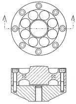
Figure 18.
Model 1111 cutaway views
This structure was a dramatic advance in the design of precision load cells, first introduced to the precision measurements community by Interface in 1969. It offered higher output, better fatigue life, better resistance to extraneous loads, a shorter load path, greater stiffness, and the possibility of compression overload protection integral to the cell.
The top view in Figure 18, with the sealing diaphragms removed, shows how the eight holes are bored down through the flexure to leave eight shear webs, formed by the material left between the holes after the boring operation.
Referring to the section through the flexure in Figure 18, the reader can visualize how the radial shear webs, along with the center hub and the outside rims on both sides, resemble two shear beam cells end-to-end. The Low Profile cell thus exhibits the stability of a double-ended shear beam, augmented by the fact that the circular design is the equivalent of four double-ended cells, thus providing stability in eight directions about the center point.
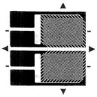
Figure 19. Shear gage
The two gages shown in Figure 18 are aligned straight across, rather than at 45 degrees because the gages themselves have their grid lines set at 45 degrees. (See Figure 19.)
Figure 18 also shows the base, bolted to the flexure around its outside rim. The base is a flat surface, guaranteed to provide optimum support for the flexure. Use of the base, or a support surface with its equivalent flatness and stability, is required to ensure the exceptional performance of the Low Profile Series. Note that the threaded hole in the base is on center, and a plug is permanently installed to seal dirt and moisture out of the space between the bottom hub of the flexure and the flat surface of the base.
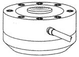
Figure 20.
Model 1211-10K
The Low Profile Series comes in both compression models and universal models. The standard configuration for compression cells is shown in Figure 20. The bolts for mounting the cell to the base are socket head cap screws, flush with the top surface, so that the load button protrudes above the top surface of the cell for clearance. The integral load button has a spherical surface, to minimize the effects of misaligned loading on the output. The seven-wire cable version is stocked, because users prefer the extra protection against moisture intrusion into the electrical system. Connector versions are available as a factory option, where the cells will be protected against the environment.
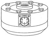
Figure 21. Model 1210-10K
The standard configuration for universal cells is shown in Figure 21. Hex head machine bolts are used to mount the cell to the base, although socket head cap screws can be provided as a factory option. The electrical connections are brought out to a PC04E-10- 6P connector on stock cells, and several connector styles are also available on special order.
Compression overload protection is available as an option on both compression cells and universal cells. It provides protection up to 500% of rated capacity on cells up to 25,000 lbf rating, and up to 300% of rated capacity on larger cells. (See our catalog for restrictions on Fatigue Rated cells.) This protection is obtained by limiting the travel of the center hub as it is deflected under load toward the flat surface of the base. (See Figure 18.) By carefully grinding and lapping the mounting surface of the cell, the gap between the hub and the base is adjusted so that the hub hits the base at about 110% of rated capacity. Any further loading drives the flat hub surface against the base, with very little further deflection. Since this total deflection is of the order of 0.001" to 0.004", this critical adjustment can be done only at the factory, where the cell is mated to the base and tested as a completed assembly.
Note
This overload protection operates only in compression and is available on both compression and universal cells, except for fatigue rated cells (see below).
The Low Profile Family is available in three major application series: Precision, Ultra Precision, and Fatigue Rated. The smaller cells, from 250 lbf to 10,000 lbf capacity, are in a package 4.12" in diameter and 1.38" thick. Intermediate capacities are contained in packages of 4.75", 6.06", 7.50", 8.00", and 8.25" diameter, from 1.75" to 2.50" thick. The largest universal cell, at 200,000 lbf capacity, is 11" in diameter and 3.5" thick.
The basic construction of all the cells in the family is quite similar. The major differences within each series are in the number of shear beams and the number of gages in the legs of the bridge. The product differentiation between the types relates to the specific application which they are designed to support.
Extraneous Load Sensitivity
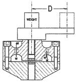
Figure 22. Moment adjustment
One process step which is standard in all Low Profile Series cells is adjustment of extraneous load sensitivity. Although the design itself cancels out the bulk of this sensitivity, Interface goes one step further and adjusts each cell to minimize it even more.
Figure 22 shows a simplified view of a moment testing setup. Assuming a weightless arm mounted on a load cell’s hub, the load cell’s flexure will be stressed by the application of weight “W” on the centerline of the cell. The stress vectors are shown as “W” in the detail in Figure 23.
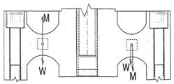
Weight and moment vectors
Notice that there is an equal “W” vector on both the right side and the left side of the flexure, because the force of the weight is on the centerline of the cell. The gages are wired into the bridge circuit so as to sum up all the force vectors acting in the same direction in the cells’ shear webs, so the weight vectors in this example are additive.
If we now move the weight to the end of the arm, “D” distance off the centerline, the cell sees the weight vectors and also a new set of vectors due to the moment “M,” the twisting action caused by the weight’s position at the end of the arm, tending to push down on the web on the right side and pull up on the web on the left side.
Remembering that the gages are connected so as to add the “W” vectors, we can see that the “M” vectors will cancel, thus not causing any output signal due to the moment. This statement will be true, of course, only if both webs are exactly the same dimension and if the two gages have exactly the same gage factor. In practice, everything has a tolerance, so the cancellation of moments probably won’t be within specified limits when the cell is first assembled. In actual practice, the test station is designed so that the arm can be rotated to any position, and each pair of webs is tested and adjusted for optimum cancellation of moments.
The Low Profile Precision Series
This series, with capacities from 300 lbf to 200,000 lbf forms the backbone of the force testing capability at companies all over the world. It features very competitive prices combined with specifications which satisfy the majority of force testing applications. It offers 4 mV/V output in 5,000 lbf and greater capacities, resistance to extraneous loads, a short load path, very low compliance (high stiffness), and a very respectable static error band specification (±0.04% to 0.07% FS).
The Low Profile Ultra Precision Series
This series, with capacities from 300 lbf to 200,000 lbf, was developed to satisfy the most demanding requirements of sophisticated testing labs. It features a very moderate price adder over the Precision Series, combined with specifications which are better than the Precision Series cells in the critical parameters, such as static error band (±0.02% to 0.06% FS), non-linearity, hysteresis, non-repeatability, and extraneous load sensitivity.
The Low Profile Fatigue Rated Series
This series, with capacities from 250 lbf to 100,000 lbf, is the industry standard in the world of aerospace fatigue testing. It features a guaranteed fatigue life of 100 million fully reversed load cycles. Although constructed in the same packages as the Precision Series, the Fatigue Rated Series has tighter specifications on resistance to extraneous loads and it offers stiffer compliance, for example, 33,000,000 lb/inch in the 100,000 lbf capacity. Since fatigue testing generally involves applying bimodal forces to test samples through the load cell, compression-only cells are not available in this series. Also, because of the cells’ very low deflections, overload protection is not available.
Most people generally have an idea about the meaning of the word “fatigue,” as it relates to the failure of a truck spring, for example. They envision the part, after thousands of hours of operation under vibration and shock loads, finally just “giving up” and failing. However, the phrase “fatigue rated,” as it applies to an Interface load cell, has a much more explicit and well defined meaning.
Fatigue Rated Load Cell
An Interface Low Profile Fatigue Rated load cell will still meet its performance specifications after being subjected to 100 million fully reversed load cycles. Also, its static overload rating is 300% in both modes, tension and compression.
The fatigue rated design was developed to support the critical testing requirements in the aircraft and space programs. Not only was it necessary to have a load cell which would survive while driving the life test of critical aircraft and missile parts, but it was also crucial that the load cell still meet the specifications during the whole test, to avoid having to repeat expensive tests due to failure of a load cell.
Another advantage of the Low Profile design was the ability to install two, sometimes three, or in some cases four electrically isolated bridges in one load cell package. Many customers used this feature to provide a backup recording of the whole test, from the “B” bridge, to verify the test in the event of a failure in the primary data chain from “A” bridge of the load cell. The “B” bridge thus is able to back up the test system for either a failure of Bridge “A” in the load cell itself or for the failure of any element in the data/recording channel for Bridge “A.”
A more technically complete explanation of fatigue as it applies to load cell flexure design is published in the Interface catalog and on the Interface Web site under .
Compression Loading
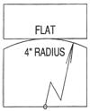
Figure 24.
Load button and plate
The application of compression loads on a load cell requires an understanding of the distribution of forces between surfaces of various shapes and finishes.
The first, and most important, rule is this: Always avoid applying a compression load flat-to-flat from a plate to the top surface of a load cell hub. The reason for this is simple: it is impossible to maintain two surfaces parallel enough to guarantee that the force will end up being centered on the primary axis of the load cell. Any slight misalignment, even a few micro inches, could move the contact point off to one edge of the hub, thus inducing a large moment into the measurement.
One common way to load in compression mode is to use a load button. Most compression cells have an integral load button, and a load button can be installed in any universal cell to allow compression loading. Minor misalignments merely shift the contact point slightly off the centerline. Figure 25 shows a major misalignment, and even the five degrees shown would shift the contact point only 3/8" off center on a load button having a 4" spherical radius, which is the type normally used on load cells up to 10,000 lbf capacity. For 50,000 lbf loading, a 6" radius is used, and for 200,000 lbf loading a 12" radius is used.
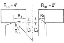
Figure 26. Typical compression foot
and check rod installation
In addition to compensating for misalignment, the use of a load button of the correct spherical radius is absolutely necessary to confine the stresses at the contact point within the limits of the materials. Generally, load buttons and bearing plates are made from hardened tool steel, and the contacting surfaces are ground to a finish of 32 µinch RMS.
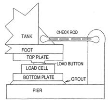
Figure 27. Indentation of correct load button
spherical radius versus smaller radius
Use of too small a radius will cause failure of the material at the contact point, and a rough finish will result in galling and wear of the loading surfaces. The half sections in Figure 26 show (in exaggerated form) the indentation radius (R1) on a flat plate caused by a load button having a 4 inch spherical radius; and the corresponding indentation (D1). The strains transmitted into the flat plate by a 10,000 lbf load are well within the specs for hardened steel. Compare that with the indentation radius (R2) and the corresponding indentation (D2). In this case, the strains could actually cause the steel to fracture.
Any one of the cells seen so far can be used in compression by mounting a load button in the cell and providing a smooth, hardened steel plate to apply the load to the cell. The disadvantage of this application is that, although the load will be supported properly for weighing, it will not be constrained from moving horizontally. The usual solution for this problem is to provide check rods which are strategically placed to tie the load to the support framework. Of course, it is essential these rods be exactly horizontal; otherwise, they will induce forces into the weighing system which don’t reflect the true loading.
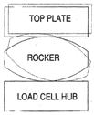
Figure 28. “Football”
self-centering system
WeighCheck™ Weighing System
The complex mountings and check rods in a compression weigh system can be replaced in most cases with the simple, innovative self storing and self-checking system developed in Figure 28 and pictured in Figure 29.
Note that, as the rocker rotates, the top plate rises. Thus, the weight of the load will tend to return the rocker to its original position. The spherical radius of the “football” can be very large, but it can be made much shorter than the equivalent round ball. The reader could imagine making a rocker by slicing a thick horizontal section out of a round ball and then gluing the remaining two pieces together.
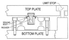
Figure 29.
WeighCheck weigh mount
In Figure 29, the rocker is modified even more drastically to remove all the unnecessary material. The only spherical surfaces that remain are at the top and bottom, to make contact with the top plate and the loading surface inside the load cell. The sealing boot is made of molded rubber, to keep dirt and water away from the lower surface of the rocker. The boot is held down against the hub of the load cell by a lip on the rocker.
There are two limit stops, one at each end of the top plate, formed by oversize clearance holes in the top plate and shoulder bolts which are screwed firmly into each end of the bottom plate. These limits operate both horizontally and vertically to contain the system in all directions.
The unique rocker provides a weigh mount with an extremely low profile, only 4" tall in the low capacities (5,000 and 10,000 lbf) and 5" tall in the high capacities (25,000 and 50,000 lbf). It is available in a tool steel version or a stainless steel version.
