
在测力环的改进思路

Introducing the Strain Gage
It is a well-known fact that the resistance of a length of wire will increase if we stretch it. Figure 6 shows an exaggerated view of a wire segment of length L1 and diameter D1. When it is stretched, it assumes length L2, and the diameter becomes D2 (smaller) to maintain the same volume in the piece. Of course, the smaller diameter of the wire means that its resistance per unit length will be higher.
Figure 6. Wire elongation under stress
If we could somehow bond a piece of fine wire onto a flexure, we could perhaps make use of this change in resistance to measure the change in length of some dimension in a load cell flexure, when a force is applied.
A practical design for such a deflection-sensitive resistance device is shown in Figure 7, magnified 10 times actual size. The vertical grid lines are the resistance wires, and are aligned with the maximum strain lines in the flexure.
The thicker ends connecting the grid lines at each end are designed to connect the grid lines without introducing resistance which would be sensitive at 90 degrees to the desired sensitive direction. Finally, the large pads are provided for attaching the wires which carry the resistance signal to the external measuring equipment.
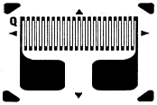
Figure 7. Simple strain gage
The grid line pattern is created optically on thin Mylar substrate which can then be bonded to the flexure at any location and with the proper orientation to respond to the forces applied to the load cell. This strain gage is the heart of the modern load cell, and it has the characteristics which we first outlined as necessary, as follows:
Thermal Tracking
Since it is bonded to the flexure with a thin glue line of an epoxy, the strain gage tracks the flexure temperature, responding very quickly to any changes.
Temperature Compensation
An added advantage is the fact that the alloy of the gage can be formulated to provide compensation for the change in modulus of elasticity (spring constant) of the flexure with temperature. Thus, the calibration constant of the load cell is more consistent over the compensated temperature range (the range of temperatures over which the compensation holds true).
Creep Compensation
It is also possible to match the creep of the strain gage to the creep of the flexure material, thus at least partially canceling out the creep effect. Interface is able to produce load cells with a creep specification of ±0.025 % of load in 20 minutes, a factor of 10 better than the uncompensated flexure material. On special order, creep performance of ±0.015% of load has been achieved.
An interesting facet of creep compensation is that, in any production lot, the compensated creep of each load cell can be positive, negative, or even zero. This happens because the gage creep can be slightly smaller than, slightly larger than, or exactly equal to the flexure creep, within the spec limits.
Frequency Response
Since the strain gage’s mass is virtually zero, the frequency response of a load cell system is limited only by the response of the flexure itself, the weight of the customer’s attached fixtures, and the bandwidth of the external amplifier.
Non-Repeatability
The strain gage is intrinsically repeatable because it is bonded to the flexure and the whole assembly becomes a monolithic structure. The major contributor to non-repeatability of a load cell system is the mechanical connections of the external fixtures.
Resolution
The major advantage of the strain gage as the deflection measuring element is the fact that it has infinite resolution. That means that, no matter how small the deflection, it can be measured as a change in the resistance of the strain gage, limited only by the characteristics of the electronics used to make the measurement. In fact, tests have been run where the load cell output appeared to be erratic simply because the system resolution was too high: someone walked by the lab bench and the force of the moving air caused the reading to shift! Of course, the appropriate resolution should always be used. Too much resolution can sometimes be worse than not enough, especially when the applied loads are erratic themselves, as in many hydraulic systems.
